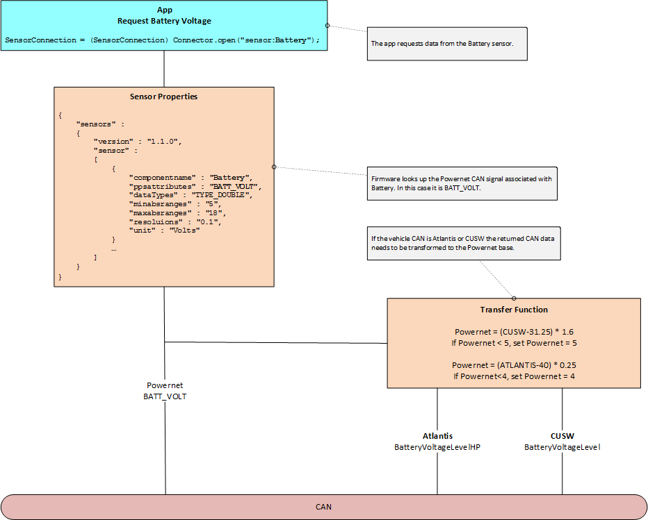
CAN Data Retrieval
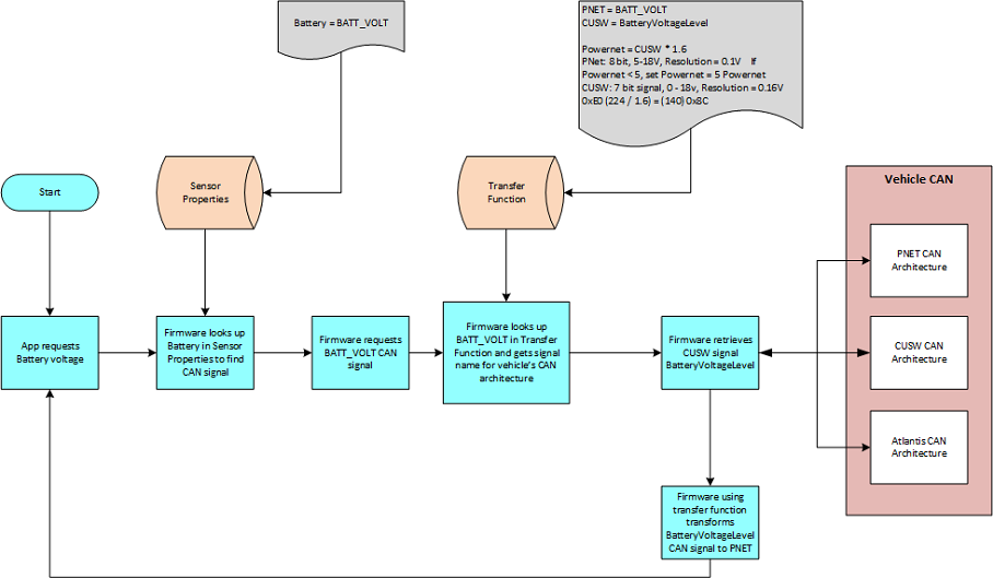
Describes how CAN data travels through the firmware to an app. The CAN data retrieval is controled by two files. The Sensor Properties file maps a sensor in the Vehicle Interface to a PowerNet CAN signal. The Transfer Functions map different CAN architectures to Powernet.
Downloads of the two control files are available on this page indicated by the ![]() symbol.
symbol.
Also reference Get Multi-Channel Sensor Data for information on sensors that measure different properties or dimensions simultaneously.
Sections:
Synchronous Retrieval Sequence
Logical sequence diagram for on-demand retrieval of the vehicle speed from the vehicle CAN bus.
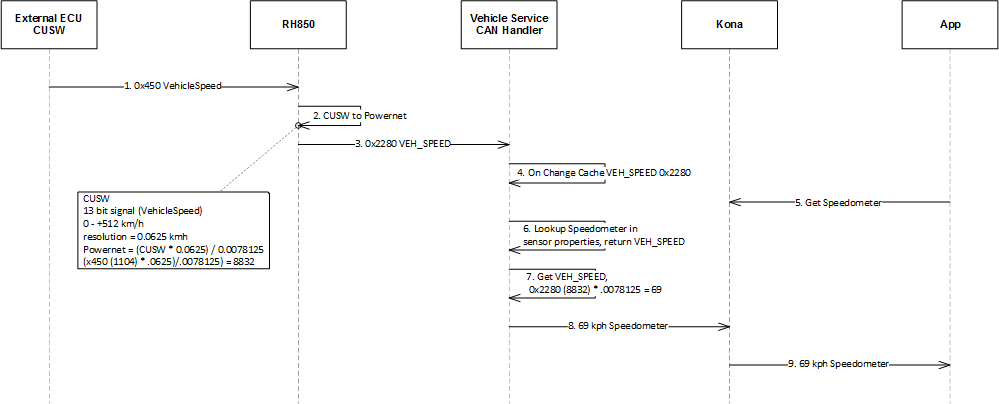
Sequence message descriptions.
Asynchronous Retrieval Sequence
Logical sequence diagrams for retrieval of battery voltage from a vehicle when the voltage changes.
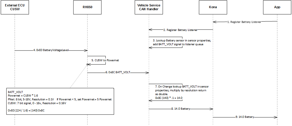
Sequence message descriptions.
Download Signal to Feature Mapping
Signal to Feature Mapping contain a mapping of connected features and the CAN signals they use.
| Model Year | Version | Change Request | File Type | Download |
|---|---|---|---|---|
| MY20 | R1 V4 | DCR 11841 | XLSX |
|
Sensor Properties contain a mapping of app sensors to CAN signals. An app will request CAN signal data using a sensor.
| Model Year | Version | Change Request | File Type | Download |
|---|---|---|---|---|
| MY20 | 1.1.0 | DCR 11841 | JSON |
|
| MY20 | 1.1.0 | DCR 11841 | XLSX |
|
| MY20 | 1.1.3 | DCR 13384 | JSON |
|
| MY20 | 1.1.3 | DCR 13384 | XLSX |
|
| MY20 | 1.1.4 | DCR 13672 | JSON |
|
| MY20 | 1.1.4 | DCR 13672 | XLSX |
|
| MY21 | 1.1.1 | DCR 12100 | JSON |
|
| MY21 | 1.1.1 | DCR 12100 | XLSX |
|
| MY21 | 1.1.2 | DCR 12792 and 12793 | JSON |
|
| MY21 | 1.1.2 | DCR 12792 and 12793 | XLSX |
|
| MY21 | 1.1.3 | DCR 13385 | JSON |
|
| MY21 | 1.1.3 | DCR 13385 | XLSX |
|
| MY21 | 1.1.4 | DCR 13673 | JSON |
|
| MY21 | 1.1.4 | DCR 13673 | XLSX |
|
Transfer Functions are used to map CUSW and Atlantis CAN architecture signals to the base PowerNet signal.
| Model Year | Version | Change Request | File Type | Download |
|---|---|---|---|---|
| MY20 | V1 R1 | SR20 1A | XLSX |
|
| MY20 | V1 R2 | SR20 2A | XLSX |
|
| MY20 | V1 R3 | DCR 11841 | XLSX |
|
| MY20 | V1 R4 | DCR 12792 and 12793 | XLSX |
|
| MY20 | V1 R5 | DCR 13384 | XLSX |
|
| MY20 | V1 R6 | DCR 13672 | XLSX |
|
| MY21 | V1 R1 | DCR 12100 | XLSX |
|
| MY21 | V1 R2 | DCR 13385 | XLSX |
|
| MY21 | V1 R3 | DCR 13673 | XLSX |
|
| MY21 | V1 R4 | DCR 13673 | XLSX |
|
Updated: 05/31/2019